3. Data on the operation of the metro in Prague and its control systems
**Data on metro operation** – The Prague metro is a large, complex system, i.e., a very complicated one. Every more complex system consists of several subsystems, links, and flows between them. Subsystems can be divided in terms of control into controlled and controlling systems. Another area is the signaling systems, which perform safety functions, i.e., mitigate risks or perform an important function whose failure or improper execution increases the risk or directly causes an accident [4]. The system of the Prague metro can generally be divided into separate operational subsystems (stations, trains, infrastructure), control systems (vehicle computers, dispatcher control centers, communication technology), and signaling systems that mitigate the impact of risks (signaling devices, signals, automatic interlocks).
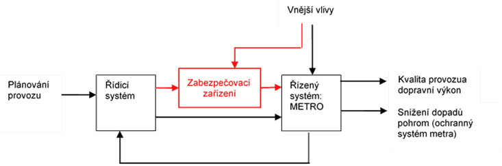
Figure 10 describes the relationships between control, signaling, and controlled systems. External influences directly affect the systems and may cause internal system failures, which can lead to hazardous events. For these reasons, signaling systems are installed between the control and controlled systems to perform safety-relevant functions. They utilize inputs from the control systems or identify unacceptable system failures or unacceptable external influences and perform their function to bring the controlled system into a safe state, i.e., a state where it does not endanger itself or its surroundings.
The metro control system, like other control systems for urban rail transport, is a distributed system. Distributed systems consist of subsystems (nodes) that perform specific functions independently without connection to others, but by linking them together, higher-level functions can be achieved. Subsystems in distributed systems thus perform some functions independently and others only after connecting multiple subsystems (nodes), forming a complex distributed system with interdependencies [4].
Regardless of the function performed, the metro subsystems can be further categorized into:
- stationary systems – track, station, and dispatch systems,
- mobile systems – trains and their equipment.
3.1 Prague Metro as a Controlled System
The control system of the Prague metro fulfills two basic functions – transportation and protective. The protective function reduces the impact of disasters. The transportation function is managed from the Urban Transport Planning Center, which sets requirements in the form of timetables and operational quality standards. These requirements are met by controlled systems, i.e., infrastructure (transportation routes and stations), transportation vehicles, and associated auxiliary systems.
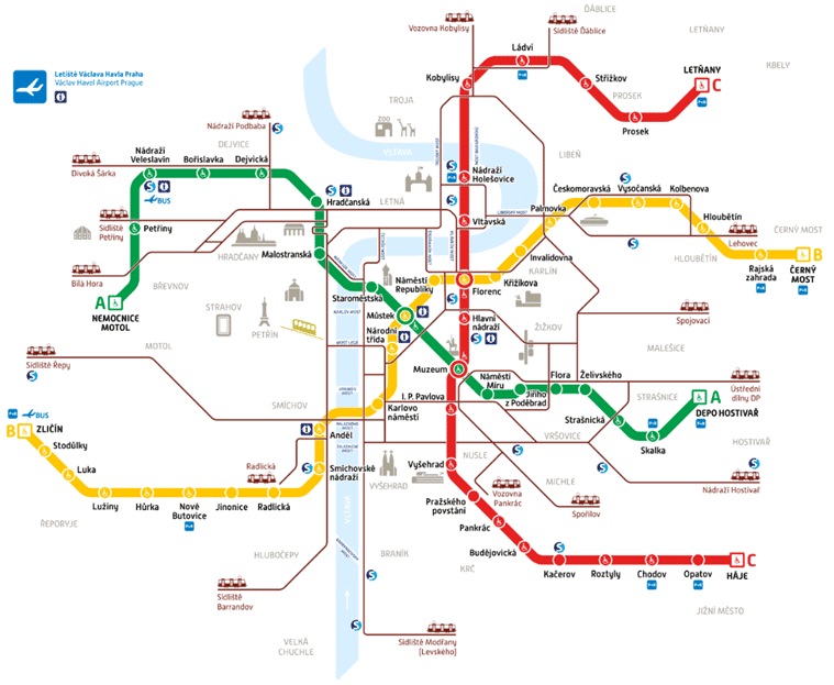
The metro network forms the backbone of the entire public transport system in Prague. Passengers can use 61 stations on three lines A, B, and C, which cover a distance of approximately 65 km [4,11]. The transportation runs on tracks located in tunnels, separated from the surrounding environment. Only in certain sections near the depots is the train operation in an open area. The track is physically separated from the surrounding infrastructure, preventing direct connections with other modes of urban and suburban transportation (commuter trains).
The fleet consists of approximately 730 vehicles, according to [11], distributed across three depots: Kačerov, Zličín, and Hostivař. Two main types of cars are used in the Prague metro, linked into five-car trains. The M1-type cars operate on line C and are dispatched from the Kačerov depot. The second type, used for lines A and B, is the 81-71M, which is a modified version of older Soviet 81-71 cars [4,11]. The layout of the metro routes is shown on the map in Figure 11.
Technologies of the controlled system consist of individual units that perform essential or supporting functions for the operation. These units are controlled either from a local control panel of the unit (so-called local control) or from a remote, centralized control center. The mentioned centers are either located in the technological rooms of the stations or at the central metro dispatch center. From the above, it is clear that the control and security systems of the metro are part of the technological section, but for the purpose of this paper, the control and security systems are divided into separate categories [4]. The technological systems of the metro according to [4,72] include:
- energy devices:
- power stations and distribution transformers (the metro station routes are powered by several 22 kV power sources, each station also has its own backup UPS source in case of a power outage, and the security and control systems also have independent power sources),
- security devices (station, track and their power supply),
- communication devices:
- communication cables,
- VHF connection with trains,
- systems for automatic passenger fare collection,
- industrial television equipment, telephone equipment, public address system,
- clock systems, fire alarm system,
- electrical security alarms,
- mechanical devices:
- escalators in stations,
- pumping stations in stations and interstation sections,
- elevators in stations,
- maintenance workshops and storage in stations,
- air conditioning systems:
- main ventilation,
- station ventilation systems,
- ASDŘ – Automated Remote Control System,
- mobile machines and equipment:
- vehicle fleet,
- equipment and means for waste cleaning, including washing and sweeping vehicles, waste containers, and a system of ladders and scaffolding for cleaning lighting equipment,
- fire protection equipment located in stations to enable rapid intervention in the event of a fire in underground spaces.
3.2 Security Devices
**Security Devices in Rail Operations**
Security devices in rail operations, specifically in metro operations, ensure the safe movement of trains on the track. Their main purpose is to reduce the risks associated with excessive train speed, incorrect setting of the route (protection against train collisions), and similar issues. Security devices are divided into three basic groups [4]:
- station security devices (SSD),
- track security devices,
- train security devices (TSD).
3.3 Metro Control System and UGTMS
**Control Systems of the Prague Metro and UGTMS**
The control systems of the Prague metro are called ASDŘ, which stands for Automated Transport Control System. While this is not entirely accurate according to European standards, it has been in use for many years in the Prague metro system. The dispatcher workplaces are located at the following positions for each metro line A, B, and C separately[4]:
- ASDŘ-D train dispatcher (for traffic control),
- ASDŘ-E energy dispatcher,
- ASDŘ-T technology dispatching,
- ASDŘ-O lighting system,
- dispatching for communication and security systems,
- firefighter dispatching,
- depot dispatching for rolling stock management.
- incorrect selection of the train’s speed or an unauthorized or unexecuted STOP command may cause an accident, such as a train collision with a person or derailment,
- incorrect passenger announcements in the station in the case of fire or other emergencies may cause panic, injury, or loss of life, thus affecting safety.
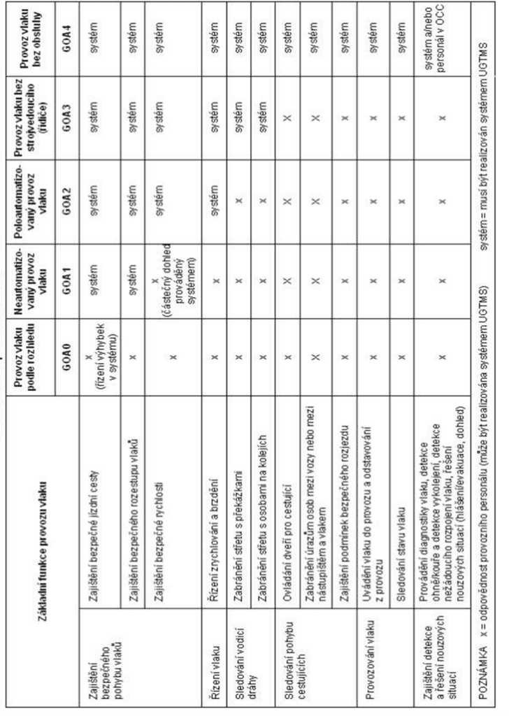
**Table 6: System Interface Requirements**
Table 6 contains the system interface requirements, i.e., it divides the basic functions of the system according to the specified level of automation. If the Prague metro is defined as a GOA2 system according to [74], the control system must fulfill basic functions to ensure the safe movement of trains and train control. Other functions may be carried out by independent subsystems. According to the EN 62290 standard, the UGTMS system (i.e., ASDŘ-D) must be capable of forming interfaces with the subsystems listed in the relevant standard, if used. Table 6 describes the interfaces, environment, and system boundaries in accordance with the aforementioned standard [74], and compares them with the actual operational state of the Prague metro; further details are available in the work [4].
Table 6 System Interface Requirements [4].
Here’s the translation with the HTML tags preserved as requested:
“`html
The function for automatic fare collection with localization and platform doors mentioned in the table is not yet installed in the Prague metro system, however, in case of further development (e.g. for the planned Route D, aiming for GOA 4), the listed functions and safety measures according to EN 62267 [75] should be considered.
see also: Smart train, metro and tramway systems | IEC
“`
I have kept all HTML tags intact and only translated the Czech text to English as requested.
| Table Legend: Bold items are used in the controlled system and are part of the control system (ASDŘ-D). Italic items are those that the control system is linked to. |
|
| ASDŘ-D (UGTMS) | Operational control equipment |
| Track equipment (includes point-to-point transmission between the track and the train) | |
| Train equipment (includes localization, speed and time measurement) | |
| Data communication system (includes data communication between track equipment, communication between track equipment and train equipment) | |
| Control | Central interface with personnel |
| Local interface with personnel | |
| Track equipment (e.g. switches, signals and signal lights, track circuits, axle counters, track equipment controlling speed, neighboring control centers, automatic stop, level crossings) | |
| Existing locking | |
| Operational planning | |
| Communication information systems | Voice communication (e.g. communication with personnel, with passengers) |
| Stations | Auxiliary equipment (e.g. elevators/escalators) |
| Fire detection/fire protection | |
| Platform/track intrusion detection (e.g. passengers on the tracks) | |
| Interface with other devices (e.g. emergency handles, emergency call devices, devices for detection/sealing of unprotected space, dispatch button/train ready for departure) | |
| CCTV monitoring | |
| Track information for passengers | |
| Voice communication | |
| Train | Doors, drive, brakes, equipment connecting the train (e.g. electrical inter-car connections) |
| Interface with train crew | |
| Obstacle detection, derailment, fire/smoke detection | |
| Unprotected space detection, equipment to close unprotected space | |
| Emergency stop handle door release/emergency button | |
| Interface with other devices (e.g. with lighting, heating, ventilation, air conditioning (HVAC), battery) | |
| Train diagnostics (for maintenance) | |
| Train status (from the perspective of readiness for operation) | |
| CCTV monitoring | |
| Information for passengers on the train | |
| Voice communication | |
| Infrastructure | Track (e.g. detection of broken rails) |
| Tunnel ventilation (e.g. fire and smoke detection) | |
| Intrusion detection system | |
| Interface with other devices (e.g. pressure seals) | |
| Traction power supply | Traction power control |
| High-voltage circuit breaker | |
| Maintenance | Maintenance system |
4.4 Transmission System of the Metro Control System and UGTMS
The general description of the metro system is based on the description of the Prague metro control system ASDŘ [4], and the European standard for defining functions and parameters of the control system for urban rail transport [74], i.e., the UGTMS system. From a technical perspective, the metro system can be divided into control, controlled, and protective or safety systems, which have mutual relationships and some shared inputs and outputs, as outlined above. The system’s input is information from the operational planning process, i.e., scheduled timetables, service schedules, etc. The system’s output is ensuring transportation performance at the required quality in transport mode and minimizing the impact of disasters in protection mode [4].
Table 7 contains the general metro system according to [4] and includes the assignment of system blocks and interfaces (technical and functional) according to UGTMS, in relation to Figure 10, Table 6, and according to [63].
Table 7 General metro system model.
| Area | Inputs | Outputs |
| Control system | external influences, operational planning, controlled METRO system | safety devices, controlled METRO system |
| Safety system | external influences, control system | Controlled system |
| Controlled METRO system | external influences, safety system, control system | control system, quality of operation and transport performance, disaster impact reduction (protective function of the metro) |
- operating control devices,
- track devices (including point-to-point transmission between the track and the train),
- train devices (including localization, speed, and time measurement),
- data communication system (including data communication between track devices and operating control devices, communication between track devices and train devices).
Here is the translation, maintaining the HTML structure as you requested:
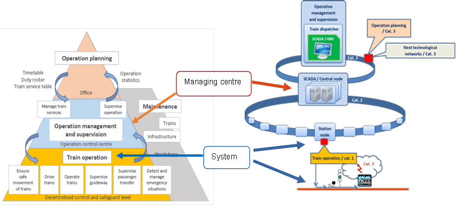
On the left side of Figure 12, the UGTMS system is divided according to the level of control (operational planning, operation control, train control), while the right side shows the actual arrangement of the ASDŘ-D system for the control of the Prague metro traffic, i.e. dispatcher workplaces connected by communication channels to the central system nodes (this layer also shows interfaces to other technological or business systems). The central nodes are interconnected by their own communication infrastructure with the station and track subsystems. The red dots on the right side of Figure 11 indicate critical communication interfaces and transmission environments according to [63]. The designation Cat. 1-3 refers to the category of transmission environment (system) according to the railway standard EN 50159 [76].
With a certain level of abstraction, the blocks of the UGTMS system and the real elements of the ASDŘ-D control system of the Prague metro [63] can be assigned to the classification of the cyber-physical system from Figure 8 in section 2.4.5:
- control center (Figure 8) – operational control device – central nodes of the ASDŘ-D system (or station control nodes),
- system (Figure 8) – track and train devices – station systems and interfaces, track access points, train communication units, train computers,
- transmission environment A, B (Figure 8) – data communication systems – dispatcher center network, station and track node network, radio transmission environment.
3.5 Results of the Analysis of Knowledge and Practice from the Railway Environment and Metro Operation
The previous work during the master’s and doctoral studies focuses on:
- Model cases (model subway station) [1,4,20,77,78],
- Case studies [10,63],
- Analysis of causes and consequences of railway accidents [16,43,73,79,80],
- Comparison of compliance between regulations, current practices in transport and industry, and legislation, with critical assessment [21,40,78,81-83],
- Top-level management with a proactive approach and integration of risk management is not properly implemented.
- There is a lack of interdisciplinary communication and connections between the layers of the SMS (Safety Management System).
- Safety requirements are not addressed comprehensively; not all significant risks may be identified.
- All-Hazard-Approach is missing in all layers of safety management.
- There is no Defence-In-Depth concept for critical objects.
- Safety and security approaches in both Czech and European legislation are treated separately, not addressing interdependencies that may affect safety.
- Railway regulations and standards do not adequately address the security of railway devices.
- Connections and flows beyond the system boundaries are not considered.
- Poor process analysis, poorly defined processes, and work instructions that do not respect modern approaches to safety management.
- Insufficient organization and inflexible organizational structure.
- Lack of knowledge of higher-layer SMS requirements or misunderstanding of them.
- Insufficient interdisciplinary communication, inconsistency in terminology.
- Insufficient monitoring, confusing information about risk sources in the system directed to higher management layers and vice versa.
- Weak links between processes and roles in the project, interdependencies between roles.
- Inadequate competence in a given role, unclear role definitions, insufficient education, training, and coaching.
- Active and passive safety elements are implemented solely based on experience, i.e., unconceptually, without defining criticality scales of activities and risks, without considering interconnections with important surrounding and superior systems; from an integral safety perspective, these represent clear system vulnerabilities.
- Unlimited system availability cannot be ensured due to the large number of entities involved in the operation under various environmental conditions; however, system availability can be improved by increasing information performance.
- Due to the interfaces of systems of different natures, the timeliness and validity of failure reports to users are significantly limited (systems have different confidentiality, availability, and integrity requirements, differing principles and measures).
- System operation continuity is influenced by system availability, meaning it also depends on information performance; each entity introduces certain uncertainties and ambiguities into the system that degrade information performance, and therefore the system’s continuity is effectively dependent on the entity with the worst information performance.
- System accuracy is always more or less limited by the scope, which is narrowed by low information performance, poor protection of information assets, and higher system complexity (difficulty).
- Problems at the human-machine interface (HMI).
- Problems at the interfaces of cyber-physical systems.
- Problems at the interfaces of socio-technical systems.
- Determination of responsibilities, not just between entities, but also between the processes of the systems, i.e., technological works.
- System and environmental heterogeneity and anisotropy – leading to hysteresis.
- System and process interfaces (HMI, cyber-physical, socio-technical, various criticalities, etc.) – different nature of interfaces and their uncertainty under certain conditions leading to failures.
- Cascade effects – leading to escalation and greater impact of failures.